A Trio of Mistakes
The MUP Astro Hat PCBs arrived from DirtyPCBs just before the weekend and they look quite nicely done.
I’ve been keeping my expectations that this will actually work in check throughout this project but with PCBs in hand, I was finally starting to believe it just might work.
Reality however had other plans.
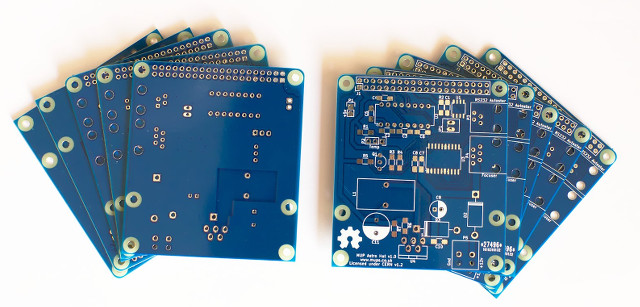
Newly arrived MUP Astro Hat PCBs
Mistake 1 - Connector Troubles
Mistake number 1, after finishing up all the soldering, sitting back to admire the finished board, taking a few photos to show others that my first attempt at SMD soldering wasn’t too bad and the through hole was pretty good, I got the comment:
“um, are you absolutely ONE HUNDRED PERCENT sure that you’ve put that header on the right side?”
The answer to that question was sadly, no, followed by a sinking feeling. Due to how the hat fits on the PI, the 40 pin connector needs to be on the bottom of the PCB.
What followed was several hours of carefully destroying the two 2x10 pin extended height header connectors to remove all the plastic leaving just the pins. Then de-soldering each pin.
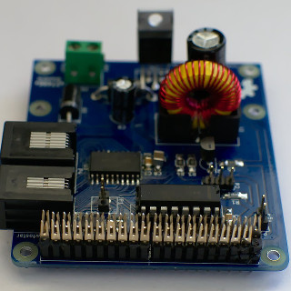
Work in progress connector destruction
Whilst slow going, that part did go without a hitch. Cleaning up the header holes to make it possible to solder in two new connectors proved trickier. The solder just wouldn’t wick out of the vias.
After quite a bit of wasted time applying flux and more solder and more flux and getting nowhere, I took a break. A cup of Tea often helps with ideas and I decided to try again but this time with flux applied not only to the pcb but also to the de-soldering braid. This made all the difference and a few minutes later all 40 holes were clear.
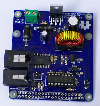
40 Pin Connector desoldered
Lesson learned (I hope)
Mistake 2 - Capacitor of Shame
This mistake occurred during the pcb layout phase. I associated the C8 capacitor with a normal 1206 surface mount footprint and only after ordering the PCBs did I realise my mistake. I’d intended to use an electrolytic cap due to the 100uF capacity needed.
I did eventually find a 100uF capacitor that would fit on the 1206 footprint but it ended up costing over £2 as opposed to a few pence.
The capacitor can be seen in the center of the board. It dwarfs the rest of the smd caps.
Mistake 3 - 1.24 Volts
With a footprint mistake and a soldering mistake out of the way, I thought i’d be home and dry but a worse mistake was soon discovered.
Applying 12v of power to the PSU then testing the output, I should have seen a nice stable 5v (well just over) but instead the meter showed a not so nice 1.24v.
After checking the resistors in the voltage divider R6 and R7 were the correct way around, reviewing the data sheet and recalculating the resistor values to ensure i’d not made a silly mistake, I was a bit stumped.
That is until it was pointed out that the feedback and Vout on the voltage divider were backwards. A mistake that occurred during the schematic layout and went unnoticed.
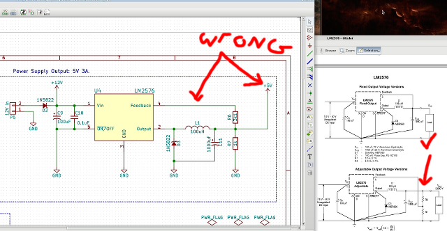
Flawed Design. Vout and Feedback lines swapped.
The feedback line was coming off of R6 and Vout was taken from the middle of the voltage divider R6/R7. This is the opposite way around to how it needs to be.
Fortunately it was possible to de-solder R7 and re-solder it at an angle between ground and R6 which resulted in the feedback line now coming off the center of the divider and Vout from the top of R6
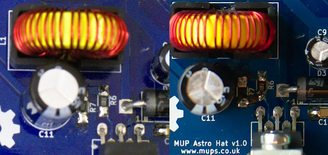
Left: Incorrect Divider. Right: Fixed Divider
With power applied again, the meter now showed 5v on the 5v line. Panic over.
Is that a new hat?
Finally the moment of truth. With the board secured on top of the Raspberry Pi and power applied I sat refreshing my router page, waiting for signs of the PI connecting via Wifi. A moment later, there it was.
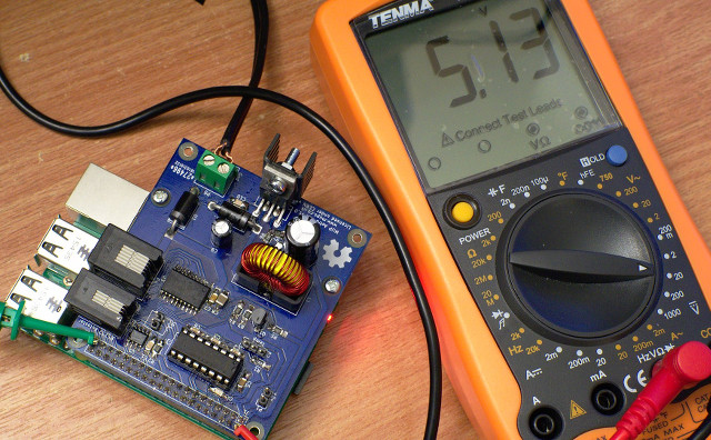
Pi running off the hat’s switch mode power supply
With the PI booting from the Hat provided 5v power supply, the first thing I wanted to verify was whether the 3 main ICs (eeprom, drv8805 and max3232) were working as I was not that confident with the soldering.
The eeprom was the quickest to test using the PI hat eeprom utils to write a file of 4096 random bytes then read it back, then write a file of all 0xFF and again read it back and compare. All tests passed.
The unipolar motor driver chip (drv8805), temp sensor and autostar rs232 still need testing as well as the performance/stability of the switch mode power supply under various loads. After that it’s onto the box mounting holes and checking for thermal issues within the enclosure.
Hopefully I’ve used up my quota of mistakes and issues for this project, at least hardware wise.
Schematic and layout files will be uploaded once I’ve corrected the design and footprint mistake and fully tested everything.
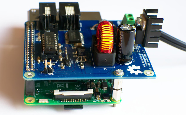
MUP Astro Hat ready for further testing.
