Astro Hat PCB
The PCB layout is now complete.
As this is the first PCB I’ve laid out and intended to have manufactured, I expect many mistakes to have been made and will be utterly surprised if it works at all, especially the switching power supply.

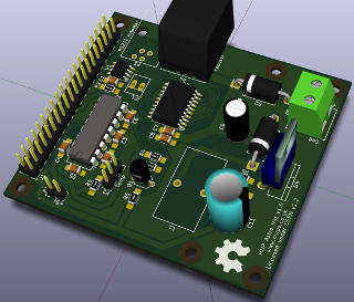
PI3 Astro Hat PCB Render
The 3D render shows the final layout with the 12v/5v power supply on the right side, connectors for the LX90 autostar and focuser nearer the top, hat EEprom (U1) and the unipolar driver/controller chip along side that and finally the RS232 level converter (through hole version) and temperature sensor header pin.
Just to the right of the temperature sensor header is the transistor Q1, to level convert the driver chips 5v to the PIs 3.3v for the /HOME signal.
There’s a few parts of the routing I’m not too happy about and I really wish I’d used a through-hole or SMD radial footprint for C8, the 100uF capacitor on the DRV8805. Complete oversight that means a £2+ ceramic capacitor (or bodging a cheap electrolytic through-hole onto the pads) as opposed to a £0.20 capacitor. Roll on revision 1.1.
Perhaps my biggest concern is the layout for the switching power supply. It’s the first time I’ve used an SMPS so I’ve stuck as close to the datasheet as possible and tried to keep the main ac loops small. Until it’s all soldered and tested under various loads I’m not going to get my hopes up. I’m also expecting the lack of test point to come back to haunt me (v1.1!).
Boards have none the less been ordered, parts have all arrived other than a yet to be ordered sealed temperature probe & cable and a few additional case mounting parts/cables.
Kicad
Kicad was used for both the schematic capture and PCB layout. No real complaints about EEschema for schematics and PCBNew is quite usable for layout. It’s not without its quirks with a few features such as differential pair routing and trace length matching only available when you switch to the OpenGL renderer. Adjusting trace width to arbitrary values instead of a predefined set of values is also restricted to GL mode.
You can’t simply stay in GL mode however as there’s other features that don’t work in the GL renderer. Since switching between is just a case of pressing F9 and F11 it’s more a minor irritation than an actual problem. It’s also a small price to pay for those additional features in an Open Source application and with more features being moved over to the GL renderer, one that will go away with time.
I last looked at Kicad a couple of years ago and it’s come a long way in quite a short period of time. There’s no question it meets my needs and with CERN becoming involved and making contributions since around 2013 the future is looking quite promising for Kicad.
I’ve made a few notes on setting changes in Kicad for use when ordering boards from DirtyPCBs. I’ll make a post about those once the boards arrive and I’ve verified the settings were actually correct.
