FPGA based 1-bit DAC
Chapter 16 of the Introducing the Spartan 3E FPGA and VHDL book ended up piquing my interest as I’ve only worked with PWM before and never heard of delta-sigma modulation. It took quite a bit of additional reading but I think I finally understand how it works and how to use it, well, the basics.
Only way to find out though was to implement it and hopefully not blow up my fpga or speaker in the process. Not that there’s a real need for doing this, the replay board has a high quality DAC on board, but never let that get in the way of experimentation.
The plan was, have 48000 samples of 8bit PCM data played back at 48kHz to produce 1 second worth of looped audio. Chapter 16 describes a 1-bit dac which I implemented in VHDL. I won’t attempt to explain how delta-sigma modulation works, I only have a basic grasp of it myself but there are quite a few videos on youtube (search for “delta sigma ADC”) and this DAC works along similar lines. From what I’ve read, oversampling helps improve the SNR of the resulting audio signal, so I left the replay boards sys clock of 49.152MHz as the clock for the dac itself.
As for the data, I used the same method as an earlier chapter described for loading a .coe file containing 48,000 8-bit PCM values into an 8 bit wide, 48000 location deep internal rom on the FPGA.
For addressing the ROM, A 30 bit counter was added (only needed 26bits in the end) and clocked at 49.152MHz. From this bits 10 and up (0 indexed) will increment at the desired 48kHz rate. The PCM rom has a 16 bit address bus, so bits 25 down to 10 were used to index it. This is where I made my first mistake.

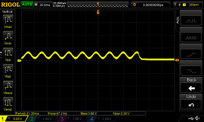
DAC PCM ROM overrun
Notice the the flatline in the signal. The ROM only has 48,000 entries, yet the address bus is 16 bit and the counter went through all 16 bits worth of values, overrunning the ROM space and causing a periodic set of 0’s to be output after every second’s worth of data. Modifying the counter so that its maximum value is 0x2EE0000 (48,000 « 10) resolved this.
For PCM data, a 1kHz sine wave .coe file was generated via c++ that output 1000 sine waves using 48 steps per wave, a total of 48000 samples or 1 seconds worth of 1kHz sine wave data when played back at 48kHz.
There are better ways to generate tones (and the clock for that matter), however as I planned to switch out the PCM data with a 1 second clip from a music file, this felt like a reasonable way to first test with a sine wave.
Another option for PCM data is to take a 1 second clip using audacity and export the audio as “other” then select “raw” and “8 bit unsigned”. The resulting aiff file can then be converted to a coe format using:
#!/bin/bash

aiff_name=$1

if [ "$#" -ne 1 ]; then
  echo "Usage: generate-coe.sh <filename.aiff>"
  echo "Aiff Format: raw, 8 bit unsigned, 48000 samples exactly"
  exit 0
fi

echo "memory_initialization_radix=10;"
echo "memory_initialization_vector="
cat ${aiff_name} | hexdump -v -e '/1 "%3u,\n"'
I used a snippet from the Bitshifter OST, it felt appropriate due to the amount of bit shifting going on.
Hardware
Aux IO pin 7 was used on the replay board for the audio output. I initially added a 1kOhm resistor to limit current draw although after working out the requirements for a low pass filter and based on parts I had to hand, I settled on a 690ohm resistor (used a 470 + 220) and a 10nF capacitor. Suitable values can be determined based on the cut off frequency required:
Where R is resistor value in ohms, C is capacitor value in Farads. Resulting cut off frequency is in Hz.
The values above result in a cutoff of ~23kHz.
A 10uF ac coupling capacitor was added after the low pass filter (the need to remove dc was fortunately pointed out to me before I hooked up a speaker) and finally a 3.5mm audio socket for speaker connection.
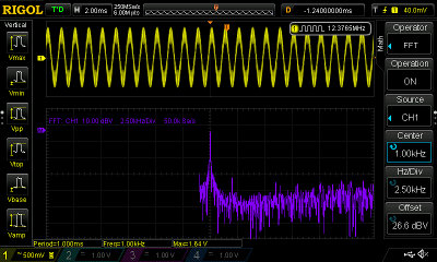
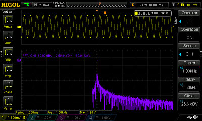
The following images show the signal probed just before the low pass filter and just after it. The 1kHz spike is clearly visible.

1-bit dac, 1kHz Sine wave, no filter

1-bit dac, 1kHz Sine wave, low pass filter
VHDL
The dac8 is pretty much straight out of the book. Took a while and quite a bit of youtube/ddging to get a clearer understanding of how delta sigma worked. Interesting tidbit, an astronomer in 1079 made use of a form of delta sigma.
entity dac8 is
    Port ( clk : in  STD_LOGIC;
           data : in  STD_LOGIC_VECTOR (7 downto 0);
           bitstream : out  STD_LOGIC);
end dac8;

architecture Behavioral of dac8 is
    signal sum : STD_LOGIC_VECTOR(8 downto 0);
begin
    -- output is the overflow bit
    bitstream <= sum(8);

    process (clk, sum)
    begin
        if rising_edge(clk) then
            -- add 8 bit data to sum, both 9 bit extended for overflow
            sum <= ("0" & sum(7 downto 0)) + ("0" & data);
        end if;
    end process;

end Behavioral;
I added a block memory IP component, 8 bits wide and 48000 entries deep. I also added a 30 bit counter to use as an indexer into the rom clocked at 49.152MHz (as is the dac8).
For the rom address indexing 16 bits are needed, these are taken from the upper bits of the counter, 25 down to 10 which results in one address change every 48,000 clocks. With a limit on the counter of 0x2EE0000. The upper bits are used as the counter itself is counting at 49.152MHz, bit 10 and up will increment at 48kHz rather than 49.152MHz had bits 15 to 0 being used.
library IEEE;
use IEEE.STD_LOGIC_1164.ALL;
use IEEE.NUMERIC_STD.ALL;

entity PCMData is
    Port ( clk : in  STD_LOGIC;
           speaker : out STD_LOGIC );
end PCMData;

architecture Behavioral of PCMData is
   COMPONENT counter30
     PORT (
       clk : IN STD_LOGIC;
       q : OUT STD_LOGIC_VECTOR(29 DOWNTO 0)
     );
   END COMPONENT;

   COMPONENT pcm_rom
     PORT (
       clka : IN STD_LOGIC;
       addra : IN STD_LOGIC_VECTOR(15 DOWNTO 0);
       douta : OUT STD_LOGIC_VECTOR(7 DOWNTO 0)
     );
   END COMPONENT;

   COMPONENT dac8
   PORT(
      clk : IN STD_LOGIC;
      data : IN STD_LOGIC_VECTOR(7 downto 0);
      bitstream : OUT STD_LOGIC
      );
   END COMPONENT;

   signal addr_index : STD_LOGIC_VECTOR(29 downto 0);

   -- cached pcm data last read from rom
   signal pcm_data : STD_LOGIC_VECTOR(7 downto 0);
   -- dac output
   signal bitstream : STD_LOGIC;
begin

   -- clocked at 49.152MHz
   dac8_out: dac8 PORT MAP(
      clk => clk,
      data => STD_LOGIC_VECTOR(pcm_data),
      bitstream => bitstream
   );

   -- 30 bit counter that resets every 2EE0000 counts.
   -- 2EE0000 is enough to index 48000 mem locations when
   -- using bits 25..10 for indexing each mem location @48kHz
   addr_indexer: counter30
     PORT MAP (
       clk => clk,
       q => addr_index
   );

   -- Read 8 bit PCM data from ROM and cache for dac
   pcm_audio : pcm_rom
     PORT MAP (
       clka => clk,
       addra => addr_index(25 downto 10),
       douta => pcm_data
   );

   speaker <= bitstream;

end Behavioral;
Constraints
For the replay board, the following constraints were used:
NET "clk" TNM_NET = clk;
NET "clk"                   LOC = "B10" | IOSTANDARD = LVTTL;
NET "speaker"               LOC = "E6"  | IOSTANDARD = LVTTL | DRIVE = 8;
With a 690 ohm resistor on the output pin, the max current should be around 5mA.
Music to my ears
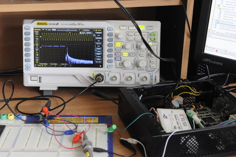
After numerous mistakes, I finally had a nice clean 1kHz sine wave output over my speaker system.

1kHz sine wave
All that was left was to swap out the PCM rom data with the 1 second bitshifter.coe. The result was a surprisingly nice sounding audio signal using headphones or over the AV receiver, better than I had expected.
The audacity screen-shot below shows the original 1 second audio clip signal on the bottom and a short recording of the output of the DAC. Note, the original clip was 44.1kHz and re-sampled to 48kHz before loading into the FPGA, likewise the recording was made at 44.1kHz as that’s the limit of my iRiver mp3 player line-in. Neither clip was normalized, so the comparison is rather limited in usefulness.

Original and DAC output signal comparison
I’ve also uploaded a 7zip file (214kB) containing the source one second bitshifter wav file and a one second recording of the dac output for comparison.
Disclaimer
Following any part of the above on an actual replay board is entirely at your own risk.
As a complete newbie as far as FPGA and the replay board hardware goes, I cannot be certain the above changes are all safe to do. There will be many non-configured FPGA pins for one, whether that could result in damage to your board or not, that’s not for me to say.
Don’t blame me if you find your board releases magic smoke :)
